The Netris Plugin
Introduction
The Netris Plugin introduces Netris as a network service provider in CloudStack to be able to create and manage Virtual Private Clouds (VPCs) in CloudStack, being able to orchestrate the following network functionalities:
Network segmentation with Netris-VXLAN isolation method
Routing between “public” IP and network segments with an ACS ROUTED mode offering
SourceNAT, DNAT, 1:1 NAT between “public” IP and network segments with an ACS NATTED mode offering
Routing between VPC network segments (tiers in ACS nomenclature)
Access Lists (ACLs) between VPC tiers and “public” network (TCP, UDP, ICMP) both as global egress rules and “public” IP specific ingress rules.
ACLs between VPC network tiers (TCP, UDP, ICMP)
External load balancing – between VPC network tiers and “public” IP
Internal load balancing – between VPC network tiers
CloudStack Virtual Router services (DHCP, DNS, UserData, Password Injection, etc…)
Supported Versions
Hypervisor |
CloudStack Version |
Netris Version |
|---|---|---|
KVM |
>= 4.21 |
4.4.0 |
Table: Supported Versions
Configuration
Prerequisites
The Netris plugin is enabled by the ‘netris.plugin.enable’ setting, which is false by default. It enables the Netris Plugin on CloudStack when it is set to true. The global setting is non-dynamic, that is, the management server would need to be restarted after being modified.
Zone creation
The CloudStack Zone creation wizard is extended:
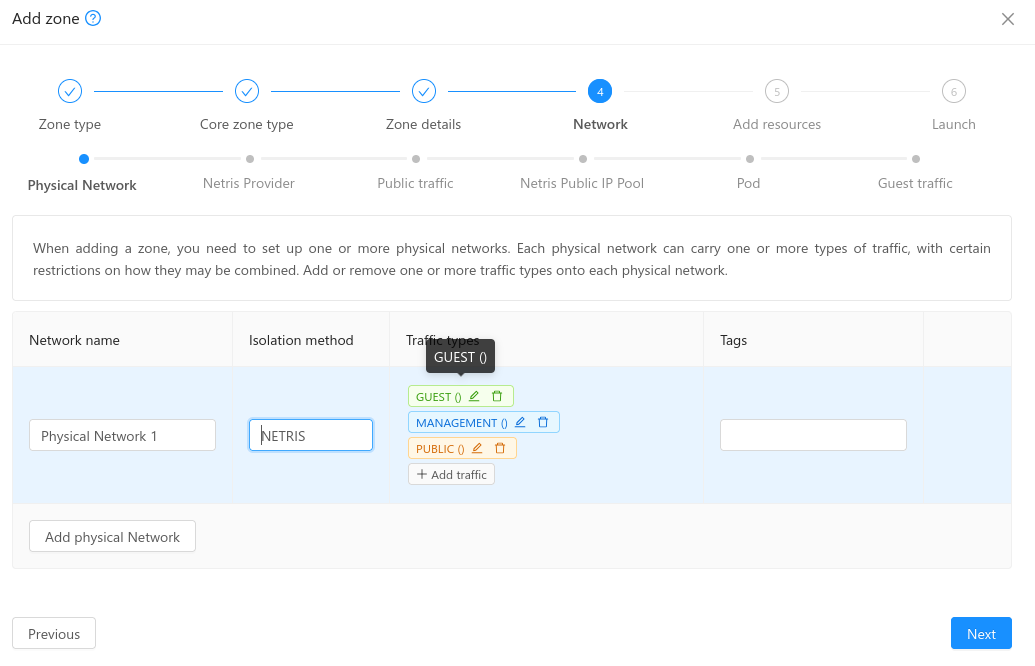
A new isolation method is added for the Core zone, with Advanced networking and KVM hypervisor: NETRIS
- When the NETRIS isolation method is selected, new steps are added to the zone creation wizard:
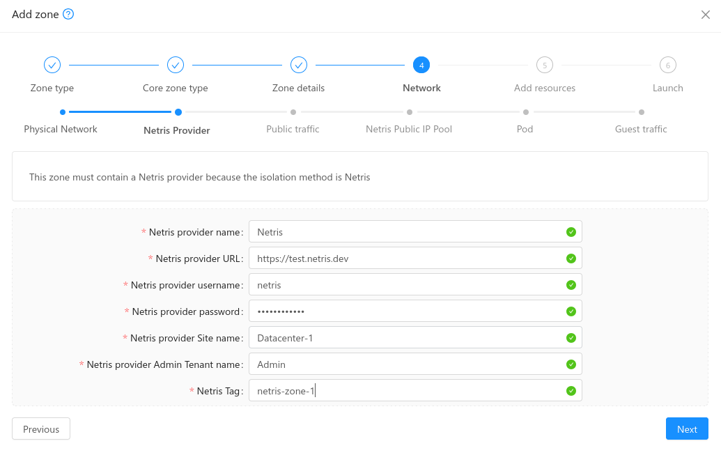
- Netris Provider: in this step the administrator must provide:
Netris provider URL along with an internal name for reference
Netris provider credentials to login into the Netris provider
Site name: The Netris Site Name to be linked to
Admin Tenant Name: The name of the Admin Tenant on the Netris provider
Netris tag: A tag to be used on each Netris VNET creation
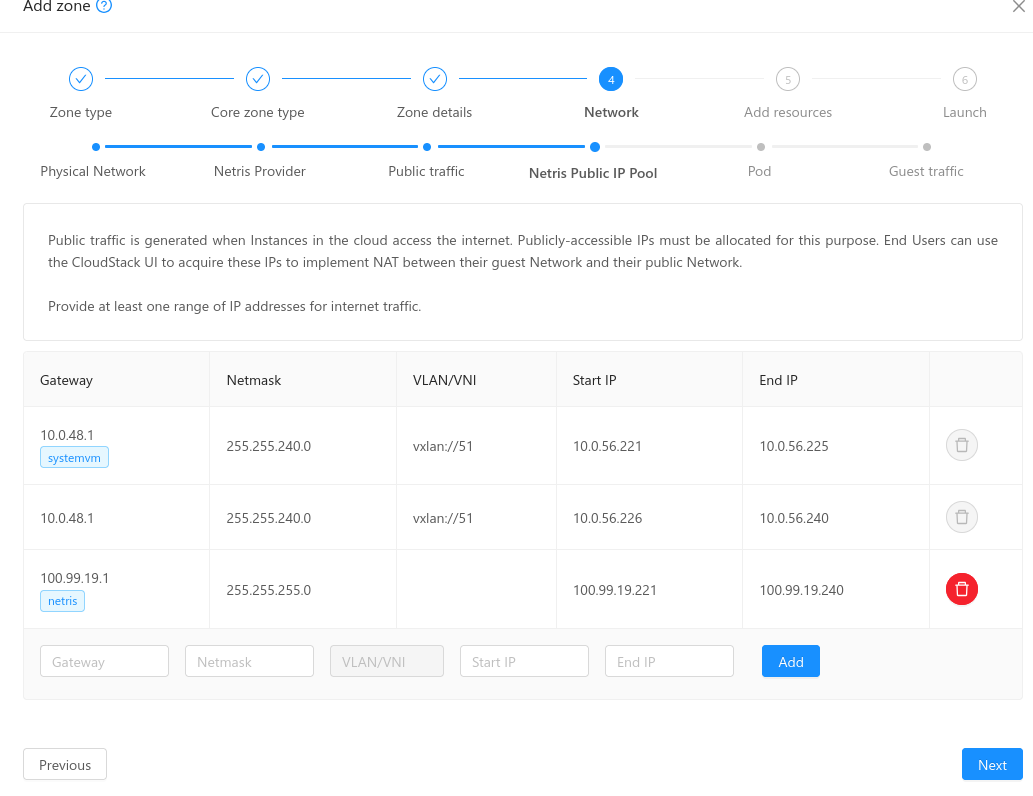
- Public traffic and Netris IP Pool: The public traffic is split in two sections.
Public traffic: The first Public IP range defined on this section will be marked for system VMs (and a tag will be displayed accordingly, with the name ‘systemvm’). The next Public IP ranges defined on this section will be available for VR Public IPs.
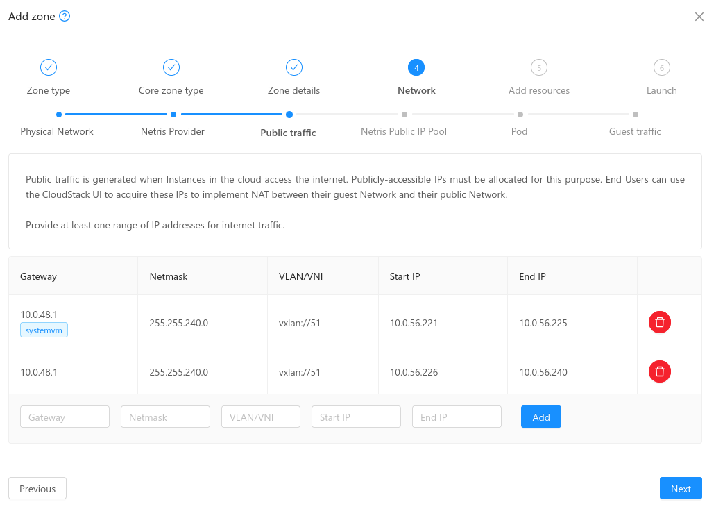
Netris IP Pool: Administrators must provide the Public IP range to be used by VPC operations: Source NAT, Load Balancing, Port Forwarding, Static NAT (this range is marked with the tag ‘netris’)
- When a new zone is being created, CloudStack will check the Public IP ranges defined and will perform the following actions on Netris:
Create an IPAM allocation for the Netris IP Pool range linked to the default VPC.
If an existing IPAM allocation contains the Netris IP Pool provided, then the range must be created as a new IPAM subnet as a child entity of the existing allocation on Netris, with purpose: ‘common’. The ‘common’ subnet purpose allows creating ‘nat’ and ‘load-balancer’ child subnets.
Note
Important: Please note CloudStack expects the public IP ranges defined in the same order as the zone wizard creation displays them. The same order must be preserved in case of adding/editing/removing public IP ranges:
System VM Public Range
VRs Public Range
Netris Public Range
The subsequent steps of zone creation remain unchanged and once the zone is successfully created and enabled, the system VMs come up with IPs from the Public IP Range reserved for System VMs (not the Netris public IP range).
VPC creation on Netris
VPC creation on CloudStack performs the following actions on Netris:
- A new VPC is created for the Admin Tenant provided at the zone creation phase, with the name convention: D<domainID>-A<accountID>-Z<zoneID>-V<vpcID>-<vpcName>, where:
domainID: Internal database ID of the domain
accountID: Internal database ID of the account
zoneID: Internal database ID of the VPC
vpcName: Name of the VPC
- A new IPAM allocation is created for the VPC Guest CIDR, with the following parameters:
Prefix: The VPC CIDR
Name: D<domainID>-A<accountID>-Z<zoneID>-V<vpcID>-<vpcCidr>, where:
vpcCidr: is the CIDR defined for the VPC
VPC: The new VPC created on the step above
Source NAT is created for VPC in NAT mode
VPC Tier creation on Netris
VPC Tier creation on CloudStack performs the following actions on Netris:
- A new IPAM subnet is created for the VPC Tier, with the following parameters:
Prefix: The VPC Tier CIDR
- Name: D<domainID>-A<accountID>-Z<zoneID>-N<networkID>-<vpcTierCidr>, where:
networkID: The internal database ID of the network tier
vpcTierCidr: is the CIDR defined for the VPC Tier
Purpose: ‘common’
VPC: The VPC created on the step above
- A new vNet is created, with the following parameters:
- Name: D<domainID>-A<accountID>-Z<zoneID>-N<networkID>-<vpcTierName>, where:
vpcTierName: is the VPC Tier name
VPC: The VPC created on the step above
VXLAN ID: A random VXLAN from the range provided on the zone creation
VLAN ID: Disabled
Tags: The tag set on the zone creation
IP Gateway: The VPC Tier gateway IP, from the subnet created on the step above.
ACLs are created on Netris
- The VPC tiers created from the default VPC network offering for Netris – Routed Mode extends the IPAM Subnet creation for the VPC Tier Guest CIDR by setting the parameter:
Global Routing = true. This parameter allows advertising the IPs for the VPC tier (required for Routed mode)
Important: Please consider at least one running VM per VPC tier to prevent VPC tier state transition to Allocated state
Supported VPC Services
- · The following operations are supported for VPCs created from the default VPC offering for Netris – NAT mode:
- Source NAT:
- A new IPAM subnet is created for the Source NAT IP of the VPC, under the Netris IP pool IPAM allocation, with the following parameters:
Prefix: <SOURCE_NAT_IP>/32, where SOURCE_NAT_IP is the VPC Source NAT IP
Purpose: ‘nat’
VPC: Default VPC
Name: D<domainID>-A<accountID>-Z<zoneID>-V<vpcID>-<vpcCidr>
- A new NAT rule is created with the following parameters:
Action: SNAT
Protocol: ALL
VPC: The associated VPC
Name: D<domainID>-A<accountID>-Z<zoneID>-V<vpcID>-SNAT
Source Address: The VPC CIDR
Destination Address: 0.0.0.0/0
SNAT to IP: true, set to the Source NAT Public IP
- Port forwarding rules:
- A new IPAM subnet is created for the Public IP, under the Netris IP Pool IPAM allocation, with the following parameters:
Prefix: <PUBLIC_IP>/32, where PUBLIC_IP is the selected free public IP
Purpose: ‘nat’
VPC: Default VPC
Name: D<domainID>-A<accountID>-Z<zoneID>-V<vpcID>-<vpcCidr>
- A new NAT rule is created with the following parameters:
Action: DNAT
VPC: The associated VPC
- Name: D<domainID>-A<accountID>-Z<zoneID>-V<vpcID>-DNAT-R<ruleID>, where:
Rule ID: The internal database ID of the port forwarding rule
Protocol: The protocol for the port forwarding rule
Source Address: 0.0.0.0/0
Source Port: 1-65535
Destination Address: The port forwarding Public IP
Destination Port: The port forwarding rule public port
DNAT to IP: <VM_IP>/32, where VM_IP: is the VM guest IP
DNAT to port: The port forwarding rule private port
- Static NAT:
- A new IPAM subnet is created for the Public IP, under the Netris IP Pool IPAM allocation, with the following parameters:
Prefix: <PUBLIC_IP>/32, where PUBLIC_IP is the selected free public IP
Purpose: ‘nat’
VPC: Default VPC
Name: D<domainID>-A<accountID>-Z<zoneID>-V<vpcID>-<vpcCidr>
- A new NAT rule is created with the following parameters:
Action: DNAT
VPC: The associated VPC
Name: D<domainID>-A<accountID>-Z<zoneID>-V<vpcID>-STATICNAT:
Protocol: ALL
Source Address: 0.0.0.0/0
Destination Address: The port forwarding Public IP
DNAT to IP: <VM_IP>/32, where VM_IP: is the VM guest IP
- Load Balancing:
- A new IPAM subnet is created for the Public IP, under the Netris IP Pool IPAM allocation, with the following parameters:
Prefix: <PUBLIC_IP>/32, where PUBLIC_IP is the selected free public IP
Purpose: ‘load-balancer’
VPC: Default VPC
Name: D<domainID>-A<accountID>-Z<zoneID>-V<vpcID>-<vpcCidr>
- A new L4 Load Balancer is created with the following parameters:
Action: DNAT
VPC: The associated VPC
- Name: D<domainID>-A<accountID>-Z<zoneID>-V<vpcID>-LB<lbID>, where:
lbID: The internal database ID of the load balancer
Protocol: The protocol for the load balancer
Frontend Address: The load balancer Public IP
Frontend Port: The load balancer public port
- For each VM added to the load balancer:
Backend address: The guest VM IP
Backend port: The load balancer private port
- ACLs
- A new ACL rule is created for each CloudStack ACL rule defined on the network tier ACL:
- Name: D<domainID>-A<accountID>-Z<zoneID>-V<vpcID>-N<networkID>-ACL<aclID>, where:
aclID: The internal database ID of the ACL rule
VPC: The associated VPC
Protocol: The selected protocol for the ACL Rule
Action: ‘permit’ or ‘deny’ matching the selected Allow or Deny action on CloudStack
- If the traffic type is Ingress:
Source Address: The ACL rule CIDR
Source Port: 1-65535
Destination Address: The VPC Tier CIDR
- Destination Port: X-Y, where:
X: The ACL rule start port
Y: The ACL rule end port
- If the traffic type is Egress:
Reverse: true
Source Address: The VPC Tier CIDR
Source Port: 1-65535
Destination Address: The ACL rule CIDR
- Destination Port: X-Y, where:
X: The ACL rule start port
Y: The ACL rule end port