The VXLAN Plugin
General
CloudStack supports VXLAN technology to enhance scalability and flexibility in networking designs.
Using VXLAN (Virtual Extensible LAN) instead of traditional VLAN (Virtual LAN) for layer 2 isolation method offers several key benefits, especially for modern data centers and cloud networking environments that require high scalability and flexibility.
VXLAN overcomes the limitations of traditional VLANs by providing a highly scalable, flexible, and efficient networking solution. It enables the creation of a large number of isolated virtual networks over a common physical infrastructure, supports better utilization of network resources through Layer 3 routing capabilities, and simplifies network management and provisioning.
When deploying a VXLAN-based network, there are two options to choose from:
Multicast
EVPN using BGP
While Multicast is the easiest to set up VXLAN isolation, EVPN offers much more control, scalability, and flexibility. Therefore, it is chosen for most VXLAN network deployments.
Warning
Deploying VXLAN, especially with EVPN, requires extensive networking knowledge, which isn’t covered by this documentation or CloudStack in general. Make sure to familiarize yourself with VXLAN, BGP and EVPN before attempting to deploy this network technology.
System Requirements / Networking for VXLAN
The following table lists the requirements for using VXLAN in your deployment:
Item |
Requirement |
Note |
|---|---|---|
Hypervisor |
KVM |
Only the BridgeVifDriver (default) is supported |
Network Card (NIC) |
VXLAN offloading |
A NIC with VXLAN-offloading support is recommended. For example Mellanox ConnectX-5 or Intel X710 |
IP Protocol |
IPv4 or IPv6 |
CloudStack is agnostic to the IP-protocol being used as underlay. Both IPv4 and IPv6 are supported |
MTU |
>=1550 |
VXLAN has an overhead of 50 bytes, therefore 1550 is the minimum. See the notes below |
BGP Routing |
FRRouting (>=10) |
BGP Routing Daemon only required for EVPN. Version >=10 is recommended |
MTU size
When new VXLAN interfaces are created, kernel will obtain current MTU size of the physical interface (ethX or the bridge) and then create VXLAN interface/bridge that are exactly 50 bytes smaller than the MTU on physical interface/bridge. This means that in order to support default MTU size of 1500 bytes inside Instance, your VXLAN interface/bridge must also have MTU of 1500 bytes, meaning that your physical interface/bridge must have MTU of at least 1550 bytes. In order to configure “jumbo frames” you can i.e. make physical interface/bridge with 9000 bytes MTU, then all the VXLAN interfaces will be created with MTU of 8950 bytes, and then MTU size inside Instance can be set to 8950 bytes.
In general it is recommend to use an MTU of at least 9000 bytes or larger. Most VXLAN capable network cards and switch support an MTU of up to 9216.
Using an MTU of 9216 bytes allows for using Jumbo Frames (9000) within guest networks.
VXLAN using Multicast
The default mode for using VXLAN is Multicast. The required configuration is described below.
Important note on max number of multicast groups
Default value of “net.ipv4.igmp_max_memberships” (cat /proc/sys/net/ipv4/igmp_max_memberships) is “20”, which means that host can be joined to max 20 multicast groups (attach max 20 multicast IPs on the host).
Since all VXLAN (VTEP) interfaces provisioned on host are multicast-based (belong to certain multicast group, and thus has it is own multicast IP that is used as VTEP), this means that you can not provision more than 20 (working) VXLAN interfaces per host.
Under Linux you can NOT by default provision (start) more than 20 VXLAN interfaces and the error message “No buffer space available” will appear in the Cloudstack Agent logs after provisioning the required bridges and VXLAN interfaces.
Increase the needed parameter to an appropriate value (i.e. 100 or 200) as required.
If you need to operate more than 20 Instances from different client networks, the change above is required.
Configure hypervisor: KVM
In addition to “KVM Hypervisor Host Installation” in “CloudStack Installation Guide”, you have to configure the following item on the host.
Create bridge interface with IPv4 address
This plugin requires an IPv4 address on the KVM host to terminate and originate VXLAN traffic. The address should be assinged to a physical interface or a bridge interface bound to a physical interface. Both a private address or a public address are fine for the purpose. It is not required to be in the same subnet for all hypervisors in a zone, but they should be able to reach each other via IP multicast with UDP/8472 port. A name of a physical interface or a name of a bridge interface bound to a physical interface can be used as a traffic label. Physical interface name fits for almost all cases, but if physical interface name differs per host, you may use a bridge to set a same name. If you would like to use a bridge name as a traffic label, you may create a bridge in this way.
Let cloudbr1 be the bridge interface for the Instances’ private
Network.
Configure in RHEL or CentOS
When you configured the cloudbr1 interface as below,
$ sudo vi /etc/sysconfig/network-scripts/ifcfg-cloudbr1
DEVICE=cloudbr1
TYPE=Bridge
ONBOOT=yes
BOOTPROTO=none
IPV6INIT=no
IPV6_AUTOCONF=no
DELAY=5
STP=yes
you would change the configuration similar to below.
DEVICE=cloudbr1
TYPE=Bridge
ONBOOT=yes
BOOTPROTO=static
IPADDR=192.0.2.X
NETMASK=255.255.255.0
IPV6INIT=no
IPV6_AUTOCONF=no
DELAY=5
STP=yes
Configure in Ubuntu
When you configured cloudbr1 as below,
$ sudo vi /etc/network/interfaces
auto lo
iface lo inet loopback

# The primary network interface
auto eth0.100
iface eth0.100 inet static
    address 192.168.42.11
    netmask 255.255.255.240
    gateway 192.168.42.1
    dns-nameservers 9.9.9.9
    dns-domain lab.example.org

# Public network
auto cloudbr0
iface cloudbr0 inet manual
    bridge_ports eth0.200
    bridge_fd 5
    bridge_stp off
    bridge_maxwait 1

# Private network
auto cloudbr1
iface cloudbr1 inet manual
    bridge_ports eth0.300
    bridge_fd 5
    bridge_stp off
    bridge_maxwait 1
you would change the configuration similar to below.
auto lo
iface lo inet loopback

# The primary network interface
auto eth0.100
iface eth0.100 inet static
    address 192.168.42.11
    netmask 255.255.255.240
    gateway 192.168.42.1
    dns-nameservers 9.9.9.9
    dns-domain lab.example.org

# Public network
auto cloudbr0
iface cloudbr0 inet manual
    bridge_ports eth0.200
    bridge_fd 5
    bridge_stp off
    bridge_maxwait 1

# Private network
auto cloudbr1
iface cloudbr1 inet static
    addres 192.0.2.X
    netmask 255.255.255.0
    bridge_ports eth0.300
    bridge_fd 5
    bridge_stp off
    bridge_maxwait 1
Configure iptables to pass VXLAN packets
Since VXLAN uses UDP packet to forward encapsulated the L2 frames, UDP/8472 port must be opened.
Make sure that your firewall (firewalld, ufw, …) allows UDP packets on port 8472, as an example:
$ sudo firewall-cmd --zone=public --permanent --add-port=8472/udp
$ sudo ufw allow proto udp from any to any port 8472
VXLAN using EVPN
Using VXLAN with BGP+EVPN as underlay is more complex to set up, but does allow for more scaling and provides much more flexibility.
This documentation can not cover all elements of deploying BGP+EVPN in your environment.
It is recommend to read this blogpost before you continue.
The main items for using EVPN:
BGP Routing Daemon on the hypervisor
No LACP/Bonding will be used
The modified script (modifyvxlan-evpn.sh) is required and this might require tailoring to your situation
BGP+EVPN capable and enabled network environment
EVPN Bash script
The default ‘modifyvxlan.sh’ script installed by CloudStack uses Multicast for VXLAN.
A different version of this script is available which will use EVPN instead of Multicast and ships with CloudStack by default.
In order to use this script create a symlink on each KVM hypervisor
- ::
$ cd /usr/share $ ln -s cloudstack-common/scripts/vm/network/vnet/modifyvxlan-evpn.sh modifyvxlan.sh
This script is also available in the CloudStack GIT repository.
View the contents of the script to understand its inner workings, some key items:
VXLAN (vtep) devices are created using ‘nolearning’, disabling the use of multicast
UDP port 4789 (RFC 7348)
IPv4 is used as underlay
It assumes an IPv4 (/32) address is configured on the loopback interface and will be the VTEP source
BGP routing daemon
Using FRRouting as routing daemon is recommended, but not required. In general FRR is a BGP routing daemon with extensive EVPN support.
Refer to the FRRouting documentation on how to install the proper packages and get started with FRR.
A minimal configuration for FRR could look like this:
frr defaults traditional
hostname hypervisor01
log syslog informational
no ipv6 forwarding
service integrated-vtysh-config
!
interface ens2f0np0
 no ipv6 nd suppress-ra
!
interface ens2f1np1
 no ipv6 nd suppress-ra
!
interface lo
 ip address 10.255.192.12/32
 ipv6 address 2001:db8:100::1/128
!
router bgp 4200800212
 bgp router-id 10.255.192.12
 no bgp ebgp-requires-policy
 no bgp default ipv4-unicast
 no bgp network import-check
 neighbor uplinks peer-group
 neighbor uplinks remote-as external
 neighbor uplinks ebgp-multihop 255
 neighbor ens2f0np0 interface peer-group uplinks
 neighbor ens2f1np1 interface peer-group uplinks
 !
 address-family ipv4 unicast
  network 10.255.192.12/32
  neighbor uplinks activate
  neighbor uplinks next-hop-self
  neighbor uplinks soft-reconfiguration inbound
  neighbor uplinks route-map upstream-v4-in in
  neighbor uplinks route-map upstream-v4-out out
 exit-address-family
 !
 address-family ipv6 unicast
  network 2001:db8:100::1/128
  neighbor uplinks activate
  neighbor uplinks soft-reconfiguration inbound
  neighbor uplinks route-map upstream-v6-in in
  neighbor uplinks route-map upstream-v6-out out
 exit-address-family
 !
 address-family l2vpn evpn
  neighbor uplinks activate
  advertise-all-vni
  advertise-svi-ip
 exit-address-family
This configuration will:
Establish two BGP sessions using BGP Unnumbered over the two uplinks (ens2f0np0 and ens2f1np1)
These BGP sessions are usually established with two Top-of-Rack (ToR) switches/routers which are BGP+EVPN capable
Enable the families ipv4, ipv6 and evpn
Announce the IPv4 (10.255.192.12/32) and IPv6 (2001:db8:100::1/128) loopback addresses
Advertise all VXLAN networks (VNI) detected locally on the hypervisor (vxlan network devices)
Use ASN 4200800212 for this hypervisor (each node has it is own unique ASN)
BGP and EVPN in the upstream network
This documentation does not cover configuring BGP and EVPN in the upstream network.
This will differ per network and is therefor difficult to capture in this documentation. A couple of key items though:
Each hypervisor with establish eBGP session(s) with the Top-of-Rack router(s) in it is rack
These Top-of-Rack devices will connect to (a) Spine router(s)
On the Spine router(s) the VNIs will terminate and they will act as IPv4/IPv6 gateways
The exact BGP and EVPN configuration will differ per networking vendor and thus differs per deployment.
Setup zone using VXLAN
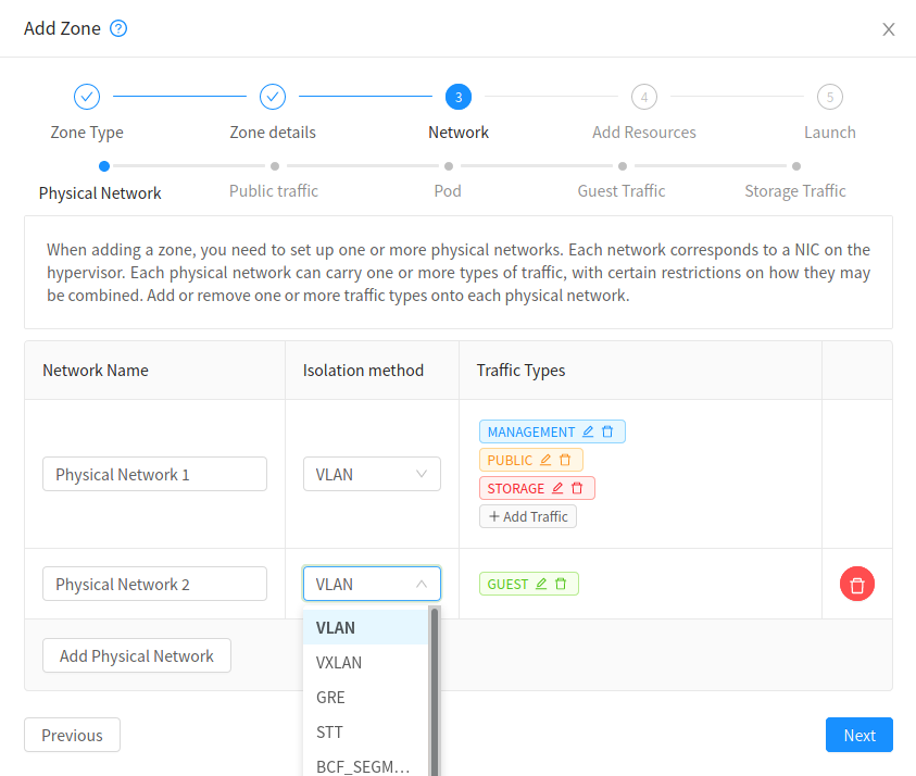
In almost all parts of zone setup, you can just follow the advanced zone setup instruction in “CloudStack Installation Guide” to use this plugin. It is not required to add a Network element nor to reconfigure the Network offering. The only thing you have to do is configure the physical Network to use VXLAN as the isolation method for Guest Network.
Configure the physical Network

CloudStack needs to have one physical Network for Guest Traffic with the isolation method set to “VXLAN”.

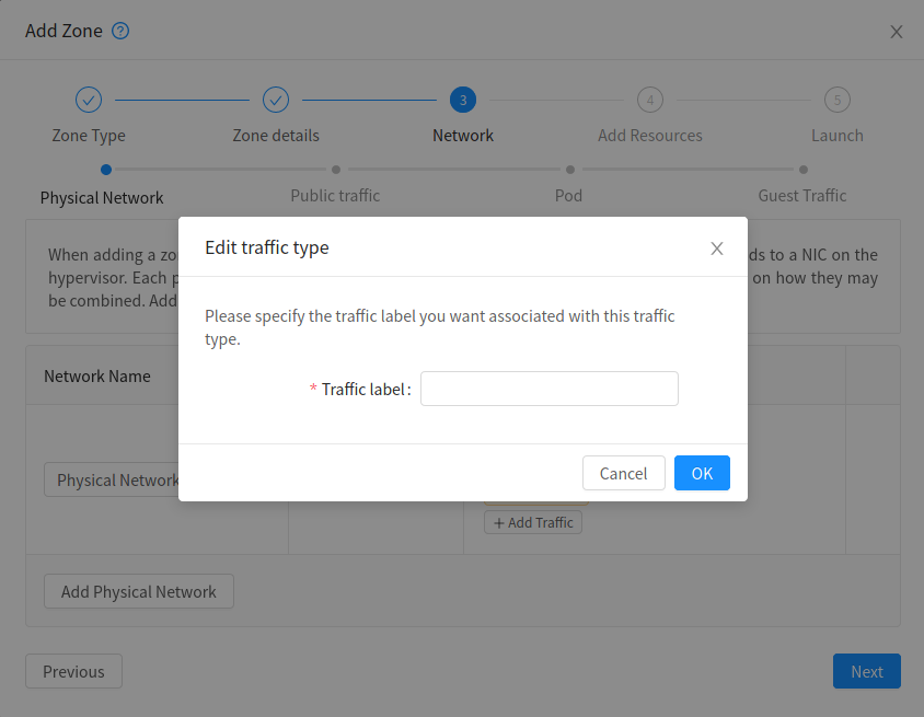
Guest Network traffic label should be the name of the physical interface or the name of the bridge interface and the bridge interface and they should have an IPv4 address. See ? for details.
Configure the guest traffic

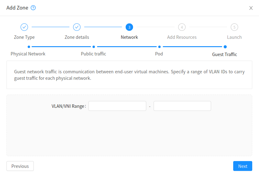
Specify a range of VNIs you would like to use for carrying guest Network traffic.
Warning
VNI must be unique per zone and no duplicate VNIs can exist in the zone. Exercise care when designing your VNI allocation policy.